

 한국어
한국어

Commercial water treatment is quietly undergoing a structural shift driven by utility rates and carbon mandates. For facilities operating continuous-filtration systems, the energy bill has historically been accepted as an unavoidable cost of doing business.
That assumption is no longer true.
Executive Summary
- High-pressure pumps consume 65% to 80% of total commercial RO system energy, making them the primary target for facility cost reductions.
- Modern low-energy (LE) membranes achieve 99.2% to 99.7% salt rejection while operating at pressures 10% to 15% lower than traditional elements.
- Implementing energy recovery devices (ERDs) and variable frequency drives (VFDs) can reduce net operational expenditures by 25% to 40% depending on source water salinity.
Many facility managers look at their water bills and blame local municipal water rates. The real culprit is almost always the mechanical friction and thermodynamic inefficiencies happening inside their own utility rooms.
The Energy-Water Tension in Commercial Filtration

Traditional reverse osmosis is an energy-intensive process by physical design. To separate pure water from dissolved solids, a high-pressure pump must generate enough force to overcome the natural osmotic pressure of the feed water. This mechanical force pushes water molecules through a semi-permeable membrane while rejecting salts, heavy metals, and organic contaminants.
In standard commercial configurations, the high-pressure pump is a massive energy sink. It typically accounts for 65% to 80% of the entire system’s electrical consumption. The remaining energy is split between feed pumps, dosing systems, control panels, and post-treatment disinfection.
Let us look at the operational contrast between unoptimized legacy systems and modern, high-efficiency configurations.
| Operational Metric | Legacy Commercial RO Systems | Modern Energy-Efficient RO Systems |
|---|---|---|
| Average Operating Pressure | 220 psi to 350 psi (15.1 bar to 24.1 bar) | 110 psi to 150 psi (7.5 bar to 10.3 bar) |
| Specific Energy Consumption (SEC) | 2.5 kWh/m³ to 4.5 kWh/m³ of permeate | 1.2 kWh/m³ to 2.2 kWh/m³ of permeate |
| Pump Control Mechanism | Fixed-speed with manual throttling valves | Variable Frequency Drives (VFDs) with pressure transmitters |
| Membrane Chemistry Type | Standard Polyamide (High-Pressure) | Low-Energy (LE) / Ultra-Low Energy (ULE) Polyamide |
| Energy Recovery Integration | Rarely present in systems under 50 GPM | Standard isobaric chambers or turbochargers |
| Average Recovery Rate | 35% to 50% (High wastewater ratio) | 60% to 85% (Concentrate recirculation) |
This performance gap represents thousands of dollars in annual operating expenses for a mid-sized facility. If you are running a system with manual throttling valves to regulate pressure, you are essentially driving a car with your foot floored on the gas pedal while controlling your speed using only the brakes. It is an engineering absurdity that remains shockingly common in mechanical rooms across North America.
Low-Energy Membranes vs. Standard Elements
Membrane chemistry is the front line of energy reduction. Traditional polyamide thin-film composite membranes require high driving pressures to achieve acceptable permeate flux rates. Low-Energy (LE) and Ultra-Low Energy (ULE) membranes modify the surface chemistry of the active polyamide layer. By increasing the hydrophilicity of the membrane surface and optimizing the polymer cross-linking density, manufacturers have altered the physical dynamics of water transport.
This structural modification allows water molecules to pass through the barrier layer with significantly less resistance.
Are there trade-offs with this approach? Yes.
Historically, choosing a low-energy membrane meant accepting a lower salt rejection rate. A standard high-pressure membrane might deliver 99.7% rejection, while an early-generation low-energy membrane would hover around 98.5%. In electronics manufacturing, pharmaceutical prep, or high-pressure boiler feed applications, that minor drop in purity could lead to rapid downstream deionization tank exhaustion.
Modern material science has largely closed this gap. Current LE membranes achieve 99.2% to 99.6% salt rejection at feed pressures that are 10% to 15% lower than their traditional counterparts.
“`
Traditional Membrane Flow Path:
[Feed Water: High Pressure (~250 psi)] —> [Densely Packed Polyamide Barrier] —> [Permeate: ~99.7% Purity]
│
└─> [High Energy Loss via Concentrate Stream]
Low-Energy Membrane Flow Path:
[Feed Water: Low Pressure (~130 psi)] —> [Hydrophilic Modified Barrier] —> [Permeate: ~99.4% Purity]
│
└─> [Reduced Pressure Drop / Lower Energy Input]
“`
When evaluating these elements for a system upgrade, engineers must calculate the balance between energy savings and downstream polishing costs. If your raw water feed has a Total Dissolved Solids (TDS) level of 300 ppm to 600 ppm, an LE membrane operating at 120 psi will easily produce high-quality permeate without overloading downstream mixed-bed DI cylinders. However, if your feed water climbs above 1,500 ppm TDS, the lower rejection rate of an LE membrane might cause a breakthrough of specific ions like silica or boron, which pass through modified polyamide structures more easily.
The Mechanics of Real-World Energy Recovery
In any reverse osmosis system, the concentrate stream leaves the membrane vessel at high pressure. In basic system designs, this high-pressure reject water is simply run through a concentrate control valve, where its pressure is dissipated as heat and friction before it goes down the drain. This represents a massive waste of kinetic energy.
Energy Recovery Devices (ERDs) capture this hydraulic energy from the high-pressure reject stream and transfer it back to the incoming feed water.
In large-scale industrial municipal plants, rotary isobaric chambers are standard. For commercial and light industrial systems, turbochargers and positive displacement recovery pumps are more common. These devices transfer pressure directly from the concentrate stream to the feed stream with mechanical efficiencies ranging from 80% to 95%.
“`
[High-Pressure Pump] ──> [Membrane Vessels] ──> [Permeate (Product)]
▲ │
│ (Boosted Pressure) │ (High-Pressure Reject)
│ ▼
[Raw Feed Water] ──> [Auxiliary Pump] ─────────> [Energy Recovery Device] ──> [Low-Pressure Waste]
“`
By routing the high-pressure concentrate back into the ERD, the main high-pressure pump only needs to supply the flow volume of the actual permeate being produced, plus whatever pressure differential is lost through the system. This reduces the motor size requirement of the primary pump by 30% to 50%.
To make this work in practice, the system must also utilize a Variable Frequency Drive (VFD). Source water temperatures fluctuate throughout the year. Cold water is more viscous and requires higher pressure to force it through the membrane. Warm water is less viscous, requiring less pressure. Without a VFD, a pump runs at a constant speed year-round, wasting energy during warmer months by relying on throttling valves to manually restrict excess pressure. A VFD automatically adjusts motor speed based on real-time feedback from pressure and temperature transmitters, keeping the system operating at its optimal thermodynamic point.
In a commercial facility in Columbus, Ohio, a manufacturing plant upgraded their process water system by replacing a fixed-speed 15 HP pump with a VFD-driven pump and low-energy membranes. The feed water temperature in this region fluctuates from 42°F (5.5°C) in winter to 74°F (23.3°C) in summer. Under the old configuration, the system wasted massive amounts of energy in the summer because operators had to throttle the pump manually to prevent membrane compaction. After the upgrade, the VFD automatically scaled back pump speed during warm months, resulting in a documented 34% reduction in annual electricity consumption for that specific utility loop.
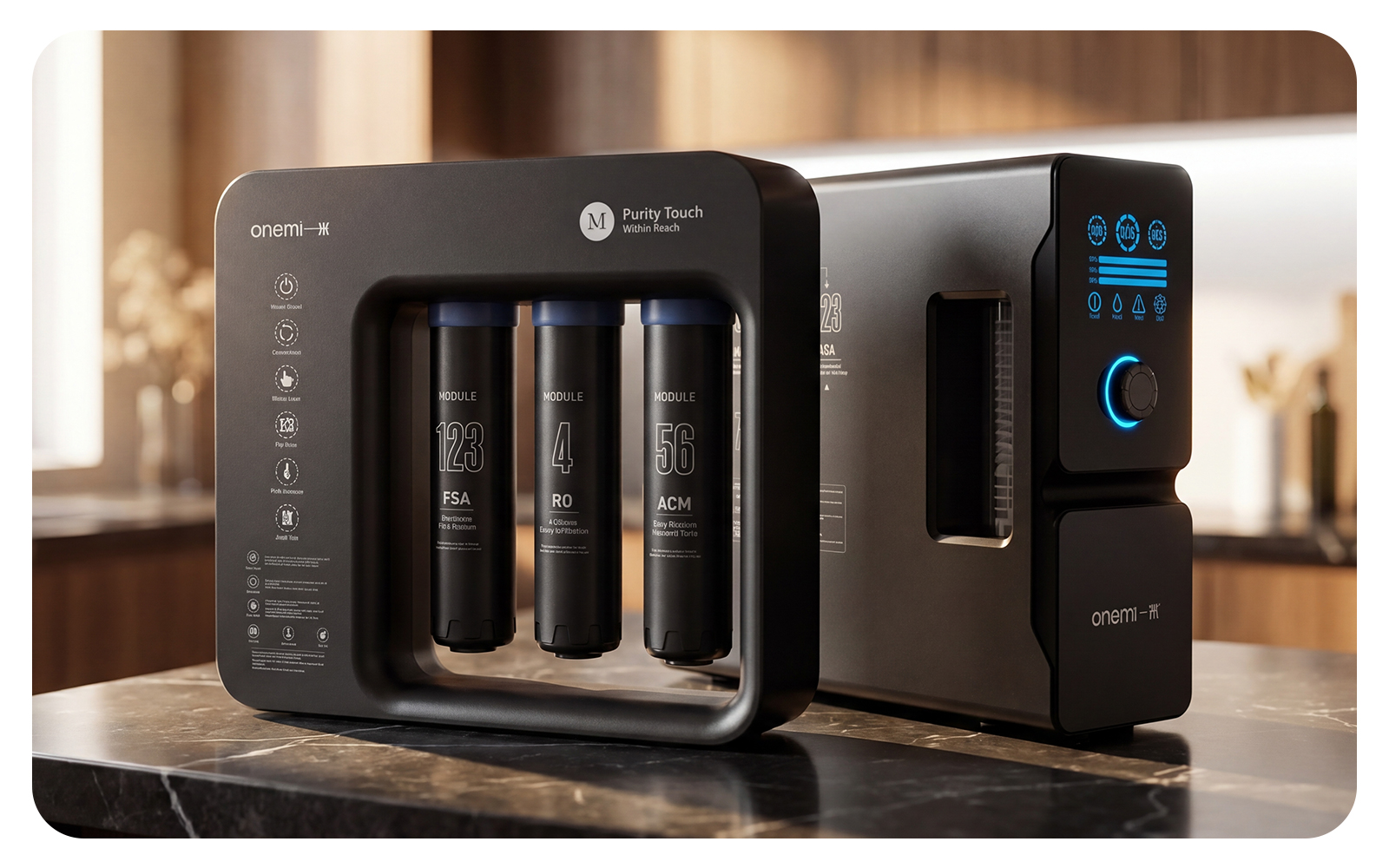
This is where brands like ONEMI are shifting the landscape. By integrating smart sensor arrays into commercial-grade water purification platforms, ONEMI systems continuously monitor temperature, feed TDS, and trans-membrane pressure to dynamically adjust pump outputs. This level of automation ensures the system is never drawing more amperage than the physical water conditions demand.
Procurement Checklist for B2B Water Systems
Procuring a commercial RO system requires looking past the initial capital expenditure (CAPEX) and focusing on the total cost of ownership (TCO) over a five-to-ten-year horizon. A cheap system with high energy consumption and rapid membrane fouling will quickly cost more than a premium, highly optimized design.
Use this structured framework when evaluating vendor proposals:
### 1. Hydraulic Design and Flux Rates
* Average Flux Rate: Ensure the design flux rate (expressed as GFD, or Gallons per Square Foot of membrane area per Day) is appropriate for your water source. For municipal tap water, look for 12 to 15 GFD. For well water, look for 10 to 12 GFD. Avoid vendors who artificially boost flow rates by over-designing the pump and running high GFDs, as this leads to rapid membrane fouling and high energy consumption.
* Array Configuration: A multi-stage system (e.g., a 2:1 array) should be utilized for recovery rates above 50% to maintain adequate cross-flow velocity across the membrane surfaces, preventing localized scaling.
### 2. Pump and Motor Specifications
* Premium Efficiency Motors: Specify NEMA Premium or IE3/IE4 efficiency class motors.
* VFD Integration: Confirm the system controller has native programming for VFD control based on pressure and temperature inputs, rather than just a basic manual speed dial.
* Pump Materials: Request 316 stainless steel pump casings and impellers to prevent corrosion and maintain hydraulic efficiency over time.
### 3. Membrane Selection
* Specific Membrane Models: Ensure the proposal lists the exact membrane manufacturer and model number. Look for reputable low-energy elements (such as DuPont FilmTec LC LE, Hydranautics ESPA, or Toray TMH series).
* Element Spacers: Request 34-mil feed spacers to reduce pressure drop through the membrane elements and improve cleanability during Clean-In-Place (CIP) cycles.
### 4. Instrumentation and Controls
* Digital Flow Meters: The system must have digital vortex or magnetic flow meters on the permeate, concentrate, and recycle lines to accurately calculate recovery rates in real-time.
* Dual TDS Monitoring: Continuous monitoring of both feed and permeate TDS is required to track rejection rates and catch membrane degradation early.
* Data Logging: The controller should log run hours, pressures, temperatures, and flows. Without historical data, troubleshooting energy spikes or fouling issues is nearly impossible.
The Realities of System Maintenance and Energy Degradation
There is a major catch that system designers rarely discuss during the sales process: energy efficiency degrades over time if maintenance is neglected.
As a membrane fouls with organic matter, scale, or colloidal particles, the feed pressure required to maintain the same permeate flow rate increases. A system that starts up operating at 120 psi may require 160 psi after six months of operation if biofouling occurs.
“`
[Fouling Cycle & Energy Impact]
Clean Membrane (115 psi Feed) ──> Organic/Scale Accumulation ──> Fouled Membrane (155 psi Feed)
│
[Energy Bill Increases ~25%] <── Increased Pump Load (Amperage Rise) <──┘
```
This represents a direct 25% increase in energy consumption. If your maintenance team does not perform regular Clean-In-Place (CIP) cycles using the correct acid and alkaline cleaners, the pump will work harder to overcome the resistance of the fouling layer.
Furthermore, running a VFD-equipped system under fouled conditions defeats the purpose of the technology. The VFD will simply ramp the motor up to its maximum frequency to meet the setpoint flow rate, consuming the same amount of power as a non-VFD system while accelerating wear on the pump wet-end.
To prevent this, commercial operators must monitor normalized permeate flow. If your actual flow rate drops by 10%, or if the temperature-corrected pressure drop across the system increases by 15%, it is time to perform a chemical clean. Waiting until the system stops producing enough water before cleaning usually means the membranes have suffered irreversible compaction or physical damage, requiring premature element replacement.
Ultimately, designing a sustainable commercial water system is about balancing mechanical control, membrane chemistry, and operational discipline. By moving away from fixed-speed, high-pressure legacy designs, facilities can lower their utility footprints while securing a reliable supply of high-purity process water.